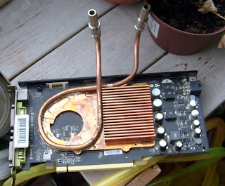
This is something I made earlier, but I never really got around to posting any pictures of it. Anyhow,,
I was going to build my own heat pipes.
The basic principles of a heat pipe is quite easy. It moves heat from one end to the other, allowing you to cool a small area with a much bigger cooler which you can put elsewhere, where there is room.
For example in a PC the CPU has a tiny surface area, and the motherboard is usually cramped for space. that limits the size of the CPU cooler you can use. but if you can move the heat efficiently somewhere where there is room, you can use a much bigger cooler.
The Heat pipe is very effective at moving heat over a distance. in fact its estimated to be 80 times more efficient than a similar size solid copper rod.
High-end Coolers today pretty much have heat pipes as standard. and it's coming along in the laptops designs as well.
Ok, so that sounds pretty high tech and desirable. but here's the thing,, it's actually quite low tech.
A Heatpipe in its most basic form is pretty much a pipe that is sealed in both ends and has a liquid inside. at one end its warm and that causes the liquid to evaporate and flow to the other end where it condenses and then runs back to the hot end thanks to gravity.
What liquid is used depends on what temperature ranges you want to use it for.
In the more hightech NASA version of a heat pipe, it also has a wick on the inside of the pipe which sucks the liquid back to the hot end, this way it can operate in zero-gravity, or at any angle.
For more information on heat pipes, just look it up on Wikipedia. =)
Anyhow, I decided to make myself a heat pipe. well it became 3 heat pipes actually.
The first one I made used water as the operating liquid.
Water evaporates at its boiling point, which is 100C at sea level pressure. this sounds like a bad idea for a heat pipe that is going to be used to cool a CPU which shouldn't get warmer than 65C (depending on make and manufacturer). But there is a trick to it.
But before I get into that, I have to post a picture to keep the readers (you) interested enough to read the rest of the text.
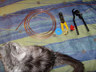
Here is the raw material and tools used.
A roll of 6mm copper tubing, solder, pliers, wick, pipe cutter, pipe bender (unused) and curious cat.(which can easily be substituted for curious dog, neighbour, brother, or anything really.)
The trick to using water, is that water boils at 100C at sea level.
But if you can lower the pressure in the pipe, it will boil at a much lower point.
The actual Trick is to heat up the water so it's boiling before you seal the pipe. Steam is (iirc) 1600 times bigger volume than normal water, so by boiling the water you get a lot of steam in the pipe, so after you seal the pipe and the water cools down and condenses, you end up with a much lower pressure in the pipe, which in turn will make the water boil at temperature lower than 100C.
I don't know the exact math for calculating how much lower the boiling point will be, but I imagine it has something to do with volume of the pipe and amount of water in said pipe.
Anyhow, I just wanted to have a go at making a heat pipe, so I wasn't bothered with details at this point.
So after doing my best to straighten a suitable length of pipe, I cut it off using a pipe cutter.
You tighten the cutter around the pipe and turn it around, tightening the cutter as you go along.
Quite handy these cutters, I highly recommend one.
A saw might get the job done as well.
Curious cat tail is optional.
So after cutting a piece of pipe, it was time to seal the ends.
There are many way's of sealing of the ends of a pipe. if you happen to have a cap that fits snugly on the top, use that.
Otherwise you can flatten the end with a pair of pliers and solder it shut, (like the back on a tube of toothpaste.)
Or, do it the way I did here.
First I dug up an old axle from some piece of dismantled,, something.
The next step was to put it in the pipe.
This is to prevent the pipe from becoming completely shut when I squeeze the end shut with the pliers.
The tool of choice here is a cable stripper which happened to have gaps suitable for this operation.
Although the picture is quite blurry, this picture should be fairly obvious.
After squeezing shut so that I end up with a small hole in the pipe end, It's time to replace the axle with something smaller, which is this screwdriver.

After squeezing it again, I end up with a tiny hole in the end of the pipe.
By squeezing it slightly below the end of the pipe, the end remains larger, thus forming a nice cone which will help keep the solder in place later on.
The next step is to insert the wick.
The wick I used for this project is solder sucking wick, which is normally used for removing excess solder.
The reason I used this wick, is because I saw a picture of a Zalman heat pipe which had been cut open. The wick used in that heat pipe looked exactly the same as this.
The wick consists of a copper braid, and looks pretty much like a candle wick, or shoelace.
I inserted the wick in one end,,,
,, and kept inserting until it poked out on the other side.
I then soldered the end shut with a small piece of wick sticking out.
Then I filled it up with about 25% water, and soldered the other end shut the same way as the first. (although not quite the same way, as I will explain later.)
The 25% ratio was something I found on a site somewhere, I don't know if it
is the best ratio to use, but it's as good as any ratio for a first attempt.
The ratio of liquid to use can always be adjusted by unsoldering, refilling and soldering it shut again.
To actually make sure I got the right amount of water, I first filled the pipe completely with water. I used a syringe which used to be an ink jet printer ink refill pack, but feel free to use any old medical equipment you might have around. the thing about syringes is that they usually have exact scales of volume printer on the side, which is quite helpful in this project.
So I just took the total amount of water, and refilled the pipe with a quarter of the total volume.
The next bit was to heat up the water in the tube until I get some steam and solder it shut.
Which sounds a lot easier than it actually was.
The thing is, to solder a pipe shut you have to heat it, when you heat a pipe with water you get steam. The steam wants out, but the end is covered with solder. so what happen's is that you get large solder bubbles, because the steam tries to escape before the solder hardens.
This is a good time to mention that hot solder bubbles popping, will splatter hot solder around, so be Careful when doing this.
Unfortunately I didn't take any pictures so you'll just going to have to imagine it, or find out if you decide to try this your self.
The Next pipe, which I made exactly the same way, was going to use Acetone as a liquid.
The reason for using something incredibly flammable as acetone in a heat pipe is quite simple, It has a much lower boiling point than water.
Acetone boils at around 56C at sea level, which makes it almost perfect for a heat pipe which you will use in a computer which is full of electrical circuits that can easily reach its boiling point.
ehm,, yeah, that sounds a bit like installing a pipe bomb in your PC.
But fortunately acetone's autoignition temperature is 465C, So It wont blow until it reaches that temperature. and if it ever does, it's most likely because your house is on fire, at which point you probably have a lot larger problems to deal with.
Anyhow, a boiling point of 56C and extreme flammability sounds like great fun.
I did the previous steps the same way I did with the water heat pipe. except for the last bit.
The last bit which involves boiling the acetone, and soldering the end shut, was done by simply putting the other end of the pipe in really hot water. since acetone boils at 56C ordinary warm tap water gets the job done.
As with the water, I had some problems with bubbles forming, with the added twist that the bubbles contain acetone vapour, and I'm trying to solder the end shut with an open flame. (I highly recommend using a soldering iron for this, and no open flames.)
But after completely failing to ignite the acetone vapour and have my face splattered with molten solder, and creating a small rocket of the pipe, spraying flaming acetone all over the kitchen, I finally got the thing shut. ( I really, really recommend a soldering iron, I didn't have one since I managed to break it while working on another project. this is something that can end badly in so many many ways.)
The 3rd, and last heat pipe for this project was going to use something even more dangerous than acetone.
Butane Gas!!!
Butane has a boiling point of 0,5C and an autoignition point of 500C
Now, I had done some research for the acetone project, and found it is quite common to use it for solar array heat pipes. but so far I haven't found any hard info on using Butane in a heat pipe.
Well, First of all, I will not be able to fill the pipe by normal means, since the butane would blow out long before I could ignite the gas with my blowtorch. never mind trying to solder it shut.
So I would have to install a gas valve on one side of the pipe.
Luckily, there are plenty of those around. In your normal cigarette lighters.
So after dismantling a lighter and removing the gas valve from it, and finding it actually fit perfectly into the pipe, I got to work.
This was actually A lot easier, because I could now seal both ends of the pipe before putting anything in the pipe.
This time I didn't use a wick, mostly because I had used it up on the other 2 pipes.
And I figure that if you are making a heat pipe for use in a PC, you can be fairly certain which way is going to be up, since a PC usually doesn't do much moving around while in use. so a heat pipe the relies on gravity should work just fine unless you install it the wrong way around later.
Here is the sealed end of the pipe with the gas valve in place.
Filling the pipe is simply like filling a lighter. with the added bonus that you can release the gas or fill more gas as needed.
The drawback is that it is tricky to know exactly how much gas you got in the pipe.
I used the normal gas cans you use to fill lighters, and made an unsuccessful attempt at weighing the pipe to keep track of how much gas i had in it. unfortunately the scale I had at hand was not accurate enough to even weigh the empty pipe, so that trick failed.
To make sure that any air inside the pipe is removed, I first filled it with some gas, and then released the gas. this should eject any air still inside the pipe.
The trick to this pipe, is to figure out how to fill just enough gas to have liquid in the pipe even when its hot. because when it gets hot all the liquid might evaporate, stopping the flow inside the pipe, making it no more efficient than a normal copper pipe.
Luckily this is easily adjusted by releasing gas or filling it with more gas.
Once the pipes was done, I did some quick and unscientific testing of them.
This was done by taking a length of normal copper pipe, a heat pipe , sticking the ends in a cup of hot water, and see how high the heat would travel on the heat pipes compared to the normal copper pipe. this was done by simply feeling the pipes, and going lower until it started to hurt. (I used boiling water in the cup.)
The heat pipes was much warmer, much higher up than the normal copper pipe. So that indicates that they actually work.
However, it still remains to see how well they will work when cooling something.
That is a project for some other day, as I then started fiddling with water cooling my PC, so I will not be using these heat pipes for this PC at least. =)
Out of the three heatpipes I made, The best one definitely seems to be using Butane gas.
It's fairly easy to make, doesn't involve creating bubbles of solder. and has the added bonus of being adjustable. (although the drawback being that its difficult to know how much gas you have in it.)
The boiling point of 0.5C is of course going to be higher after you filled it, since the pressure inside the pipe will be higher. I don't know what the pressure or temperature will be, but I'm sure the internet knows.
One other thing.
Don't get too hung up on boiling points, since even water evaporates at room temperature if given enough time. heating it up just makes it evaporate much faster, and even boiling water takes time to evaporate. It is however a good indicator of what temperature ranges the pipe will be best suited for.
At the moment, I'm quite happy with the water cooling I have in my PC.
But be assured, this is not the last heat pipe project from me. Eventually I will get around to building a silent system, and heat pipes will definitely be integral in that project.
Meanwhile,, don't blow yourself up, Always play it safe! (heh., that's definitely going to make some anti-terrorist filters kick in, if they haven't already. =)